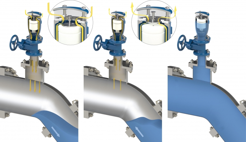
CSA RFP technology
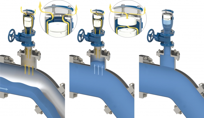
The CSA RFP technology can be considered like some sort of air bag for pipelines and is based on the purpose of ensuring unrestricted flow of air in during vacuum, to provide the same degree of protection of a standard air valve during critical operations like pipe draining, burst of pump failure with the forth functions or RFP mechanism being triggered only in case of excessive air out flow, to prevent the valve from being slammed shut from water during the closing phase. RFP can be used everywhere except for those sections of the pipe where column separation may occur and exposed to severe negative pressure conditions.
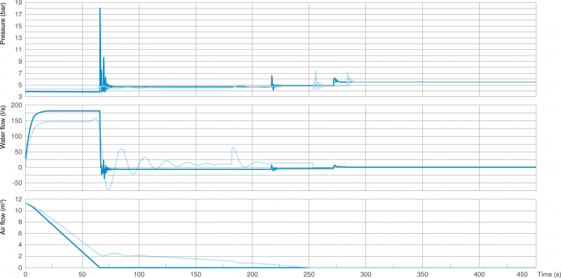
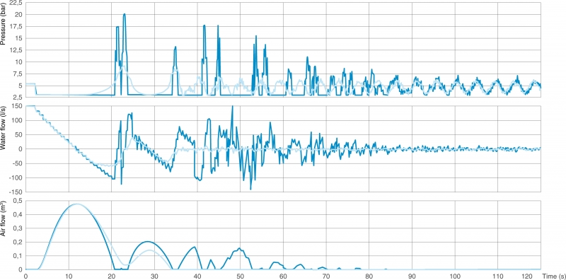
Below particular of pressure measurements taken on a pipeline subject to rapid filling with frequent failures due to the water hammer generated by conventional combination air valves, depicted in dark blue, and with CSA 3F RFP, light blue, necessary to solve the problem.
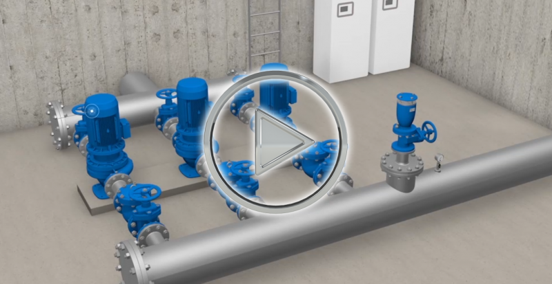
See the animation showing the functioning of RFP air valves:
CSA AS technology
The CSA AS technology, first introduced on the market by CSA, is obtained by an automatism composed of a metallic disk, spring and shaft, and located on top of CSA air valves therefore never in contact with the liquid thus maintenance free. As soon as negative pressure conditions occur the disk is pulled down and air will enter through the main orifice unrestricted. Upon termination of the negative pressure phase the spring will pull up the flat, allowing air outflow through adjustable orifices and creating the anti surge protection with the effect of reducing the water column approach and acceleration towards the air valve. The anti slam or anti-shock technology is definitely the safer choice under many circumstances.
Below particular of pressure measurements taken on a pipeline subject to frequent pipe failures due to the water hammer generated by pump cycles, depicted in dark blue, and with CSA 3F AS in light blue, necessary to solve the problem.
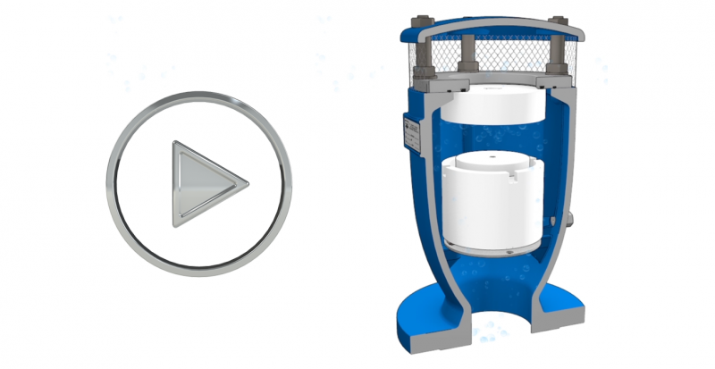
See the animation showing the functioning of AS air valves: